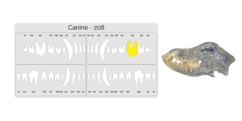
Step One. Identify the correct teeth.
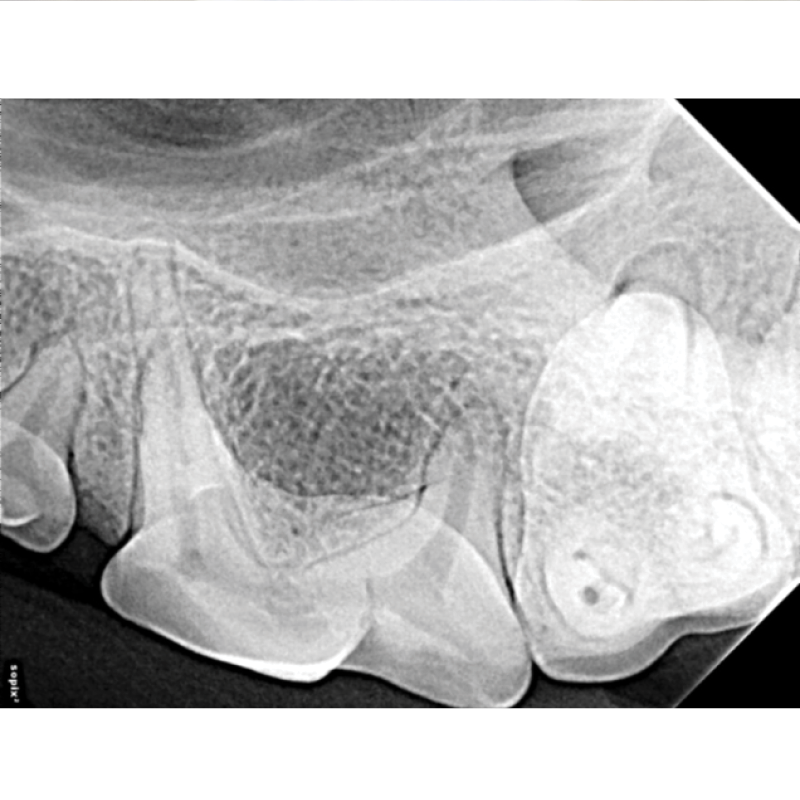
The next image taken is the last premolar 208. Highlighted on the dental chart and outlined in the picture below.
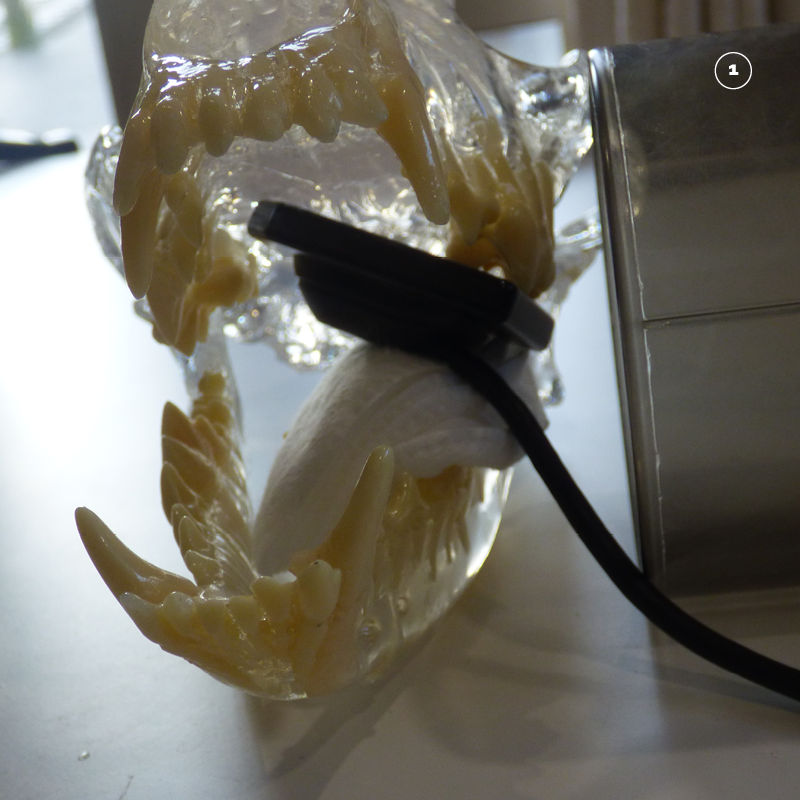
Step Two. Placing the sensor.
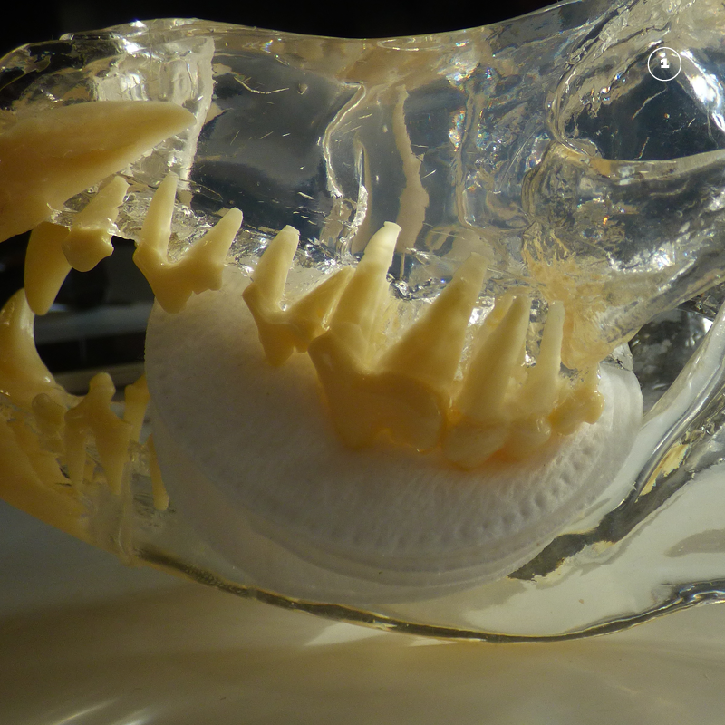
Make a cradle to hold the sensor in place by placing some swabs below 208 on top of 308 and 309 and 310.
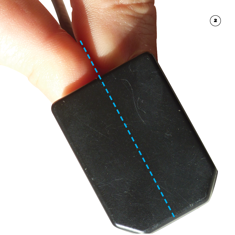
Hold the sensor with the forefinger and thumb and imagine the line between them extends along the sensor. This will help you position it correctly.
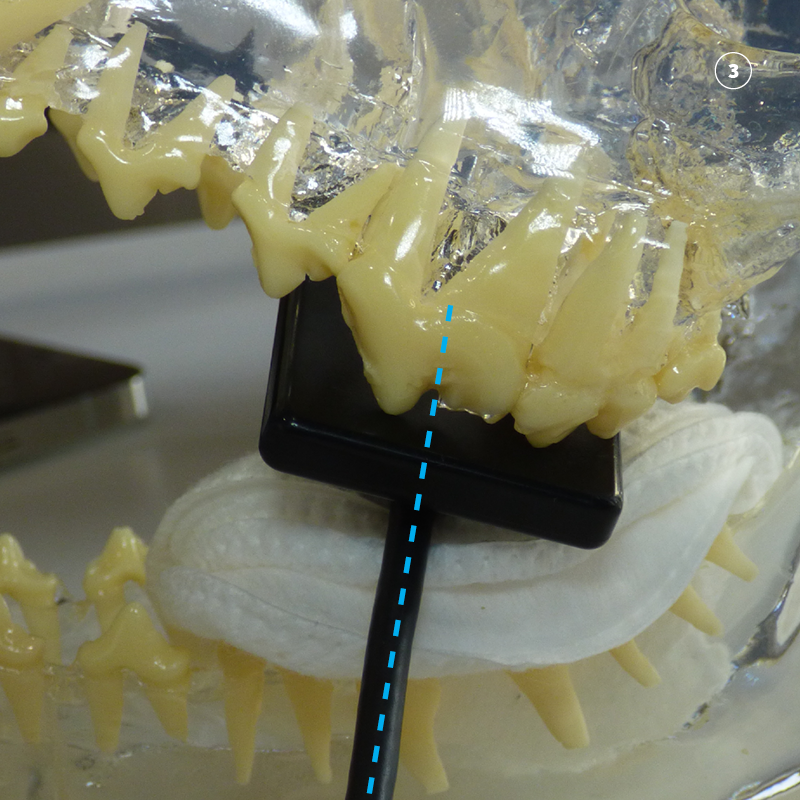
The sensor is placed in the mouth with the central line running through the base of the developmental groove. Use the line between your forefinger and thumb to help place the sensor correctly. Once placed the wire can be used to check that the sensor is in the correct place.
Step Three. Position the tube head opposite the sensor so that the beam covers the sensor.
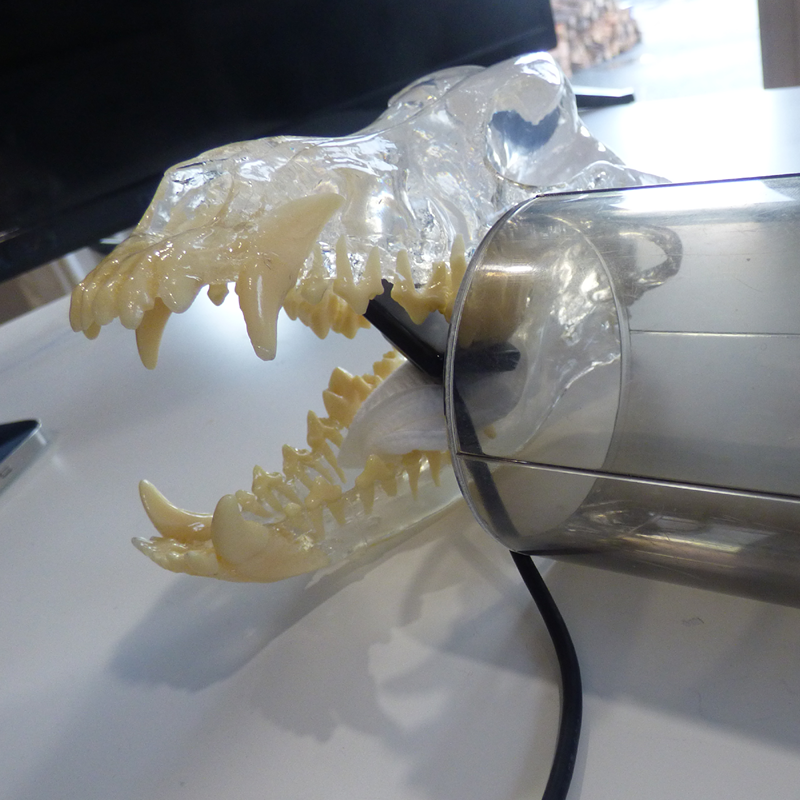
Place the cone opposite the sensor. Make sure that the entire cone covers the sensor. See through cones make this easy as you can look through the cone to see the sensor and teeth. Sometimes its necessary to retract the lips to see the sensor in the open mouth.
With a see through cone the wire from the sensor can be lined up with the central line of the cone to ensure the beam covers the whole of the sensor.
Step Four. Roll the tube head to the correct angle.
As the beam is already aligned with the sensor. Calculate the correct angle using the bisecting angle technique and roll the tube head up to the right position.
Start by visualising the view from a rostral aspect.
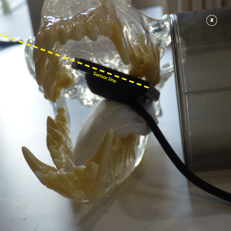
Visualise a line that moves along the sensor from the outside left of the mouth inwards. This is the long side of the sensor. Marked in yellow.
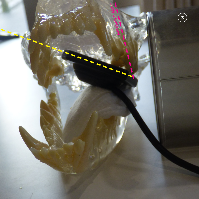
Next visualise a line through the centre of the tooth from cusp of the crown to apex of the root. Marked in Pink.
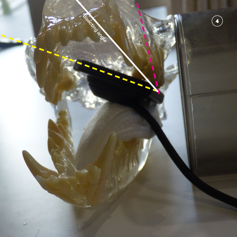
Bisect (half) the angle between the yellow sensor line and the pink tooth line. Marked in white.
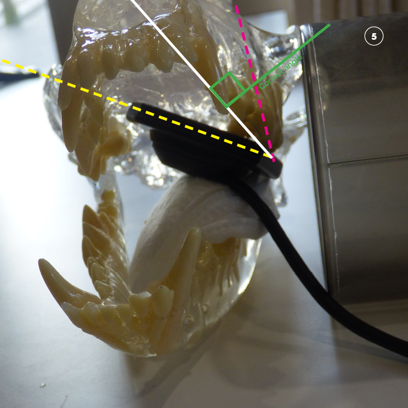
The correct angle is then calculated as perpendicular (90 degrees to) the white line that bisects (half’s) the angle of the sensor line (yellow) and the tooth line (pink). Marked in green.
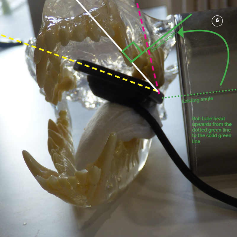
The tube head can then be rolled up to the correct angle.
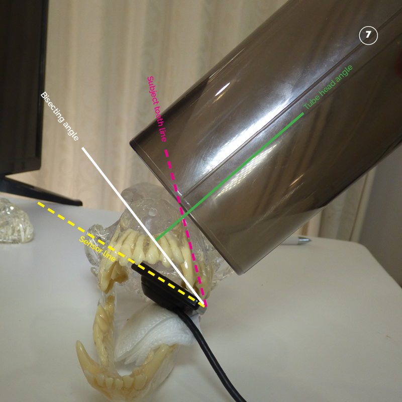
Tube head rolled up to the correct angle.
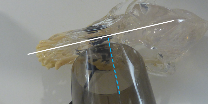
Step Five. Tube head orientation to patient mid-line.
The standard orientation buccal view of 208 is perpendicular to the mid-line.
Step Six. Radiation factors.
The standard factors with a digital sensor are as follows:
| Patient Size | Location | KV | MAS |
| <= 15 Kg | Maxillary Premolar 208 | 60 | 0.160 |
| > 15 Kg | Maxillary Premolar 208 | 60 | 0.200 |
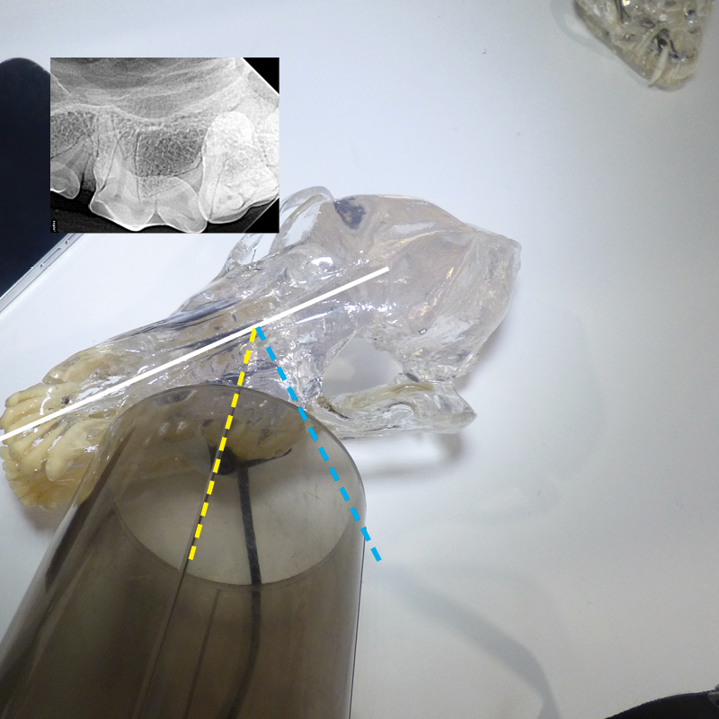
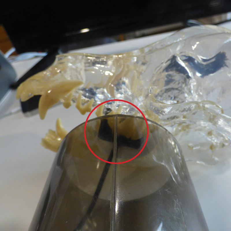
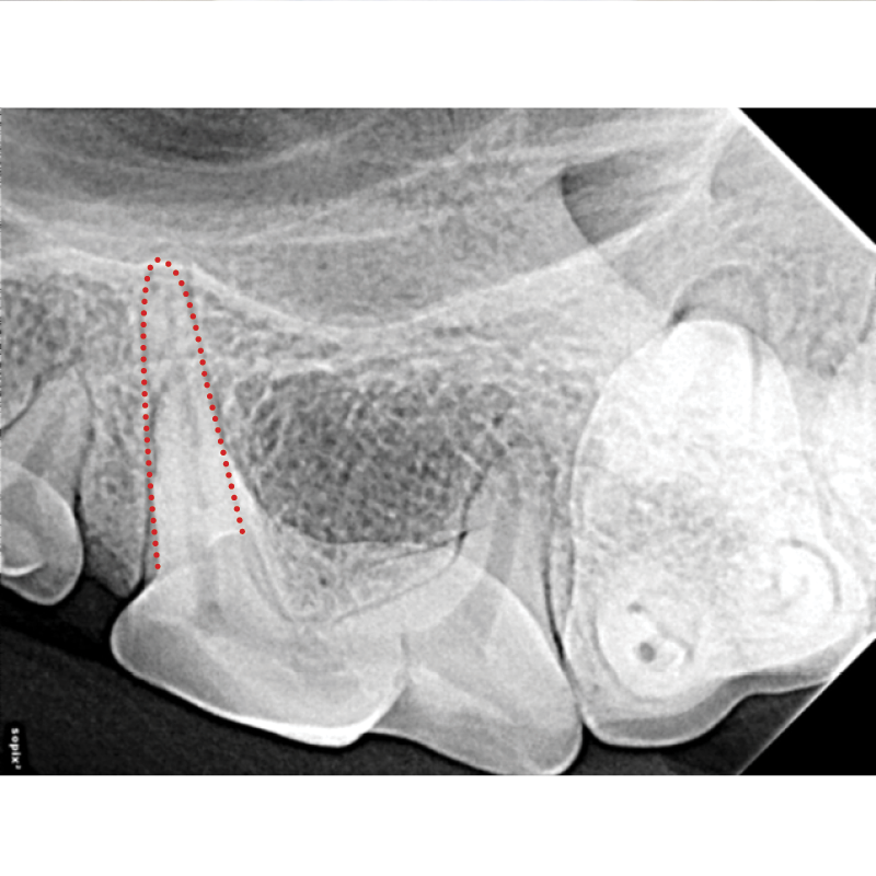
IMPORTANT! 2nd view of 208 to view 3rd cranial root.
It is very easy to expose a second image of 208 to view the 3rd cranial root if required. This is hard to see on the standard view as it is superimposed underneath the buccal root.
Marked with the red dotted line.
Leave the sensor in the mouth as it is already in the correct location with its center line opposite the base of the developmental grove.
The angle of the tube head is also correctly set using the bisecting angle technique.
Simply change the relation to the midline.
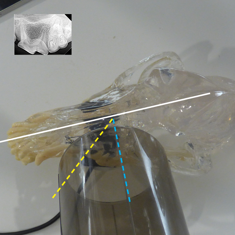
Remove the superimposition and bring the 3rd cranial root into view the orientation of the tubehead is changed from perpendicular to the mid-line to 45 degrees rostral to the mid-line.
Change from the blue dotted line to the yellow dotted line.