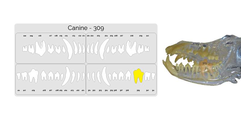
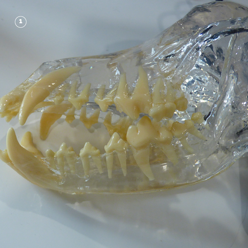
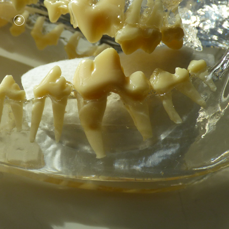
Step One. Identify the correct teeth.
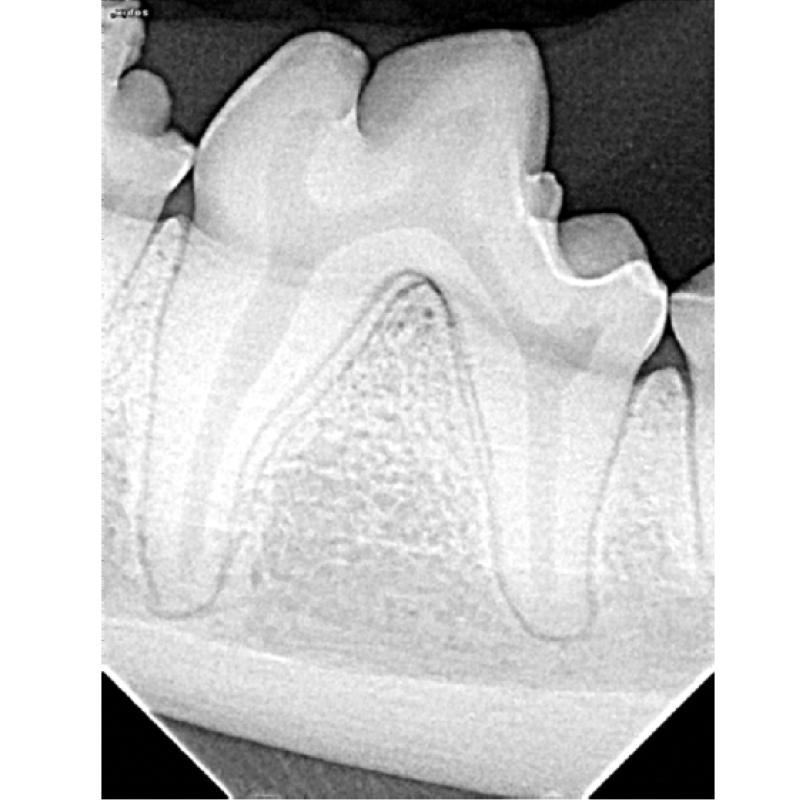
The Next image taken is of the mandibular premolar 309. Highlighted on the dental chart and outlined in the picture below.
Step Two. Placing the sensor.
Place the patient in lateral recumbancy.
Make a cradle to hold the sensor by placing some swabs directly behind 309.
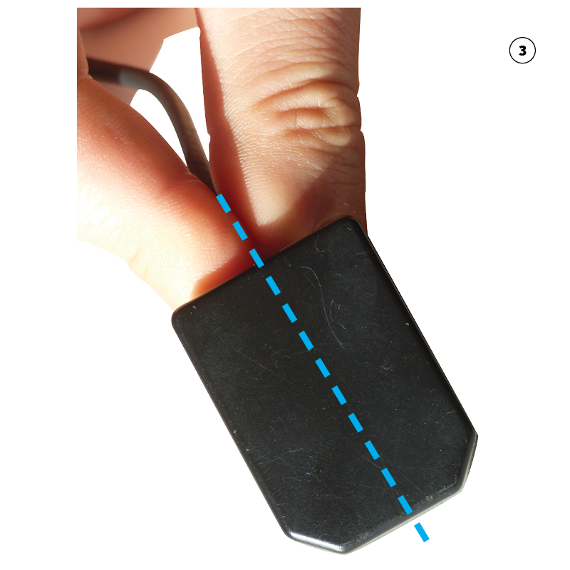
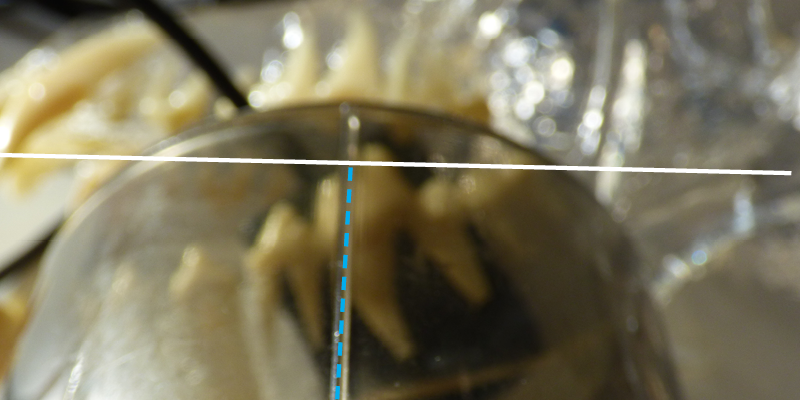
Hold the sensor with the forefinger and thumb and imagine the line between them extends along the sensor. This will help you position it correctly.
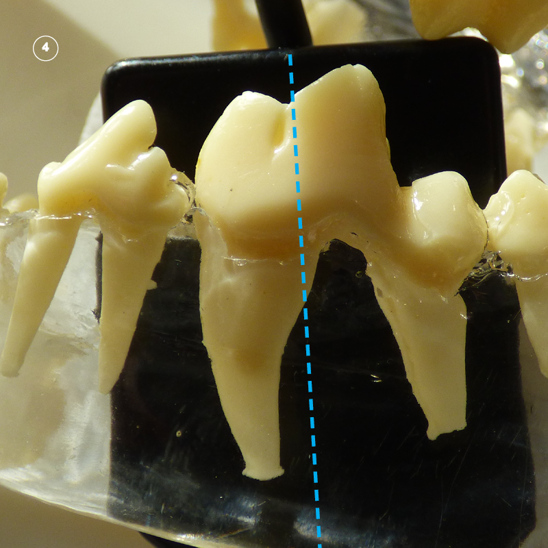
Place the sensor behind tooth 309 ensure that the central line of the sensor runs down from the top of the developmental groove. This will ensure that the sensor is central to the tooth.
Step Three. Position the tube head opposite the sensor so that the beam covers the sensor.
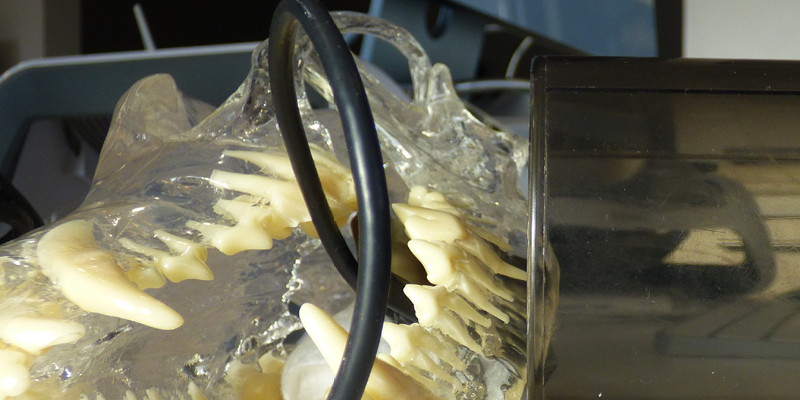
Place the cone opposite the sensor. Line up the center of the cone with the center to the top edge of the sensor where the wire comes out. This will ensure that the beam completely covers the sensor.
Step Four. Roll the tube head to the correct angle.
As the beam is already aligned with the sensor simply roll the sensor up so that the it is directly perpendicular to the sensor. This ensures that the generator is parallel to the sensor. Hence the name the parallel technique.
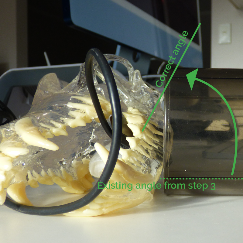
The tube head can be rolled up from its position covering the sensor from step three to the correct angle marked with the solid green line.
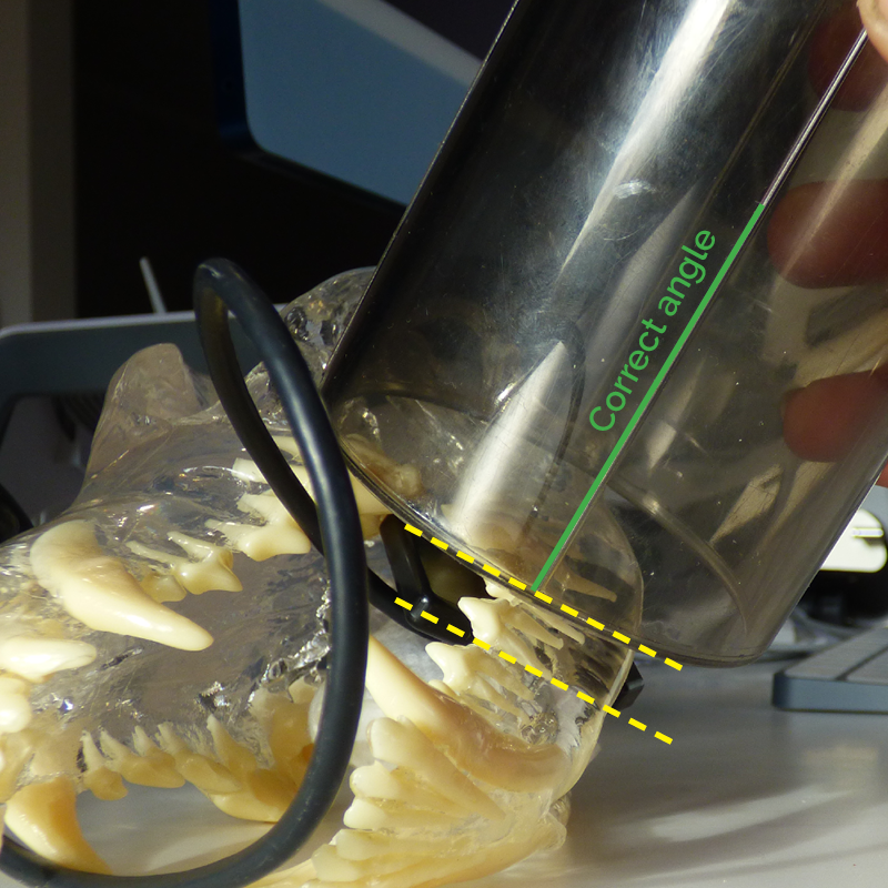
When the tube head is in the correct angle the base of the cone is parallel to the sensor. Marked with the two yellow lines.
Step Five. Tube head orientation to patient mid-line.
The standard relationship for tooth 309 is perpendicular to the mid-line.
Step Six. Radiation factors
The standard factors with a digital sensor are as follows:
| Patient Size | Location | KV | MAS |
| <= 15 Kg | Mandibular Premolar 309 | 60 | 0.125 |
| > 15 Kg | Mandibular Premolar 309 | 60 | 0.160 |