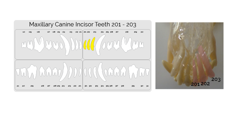
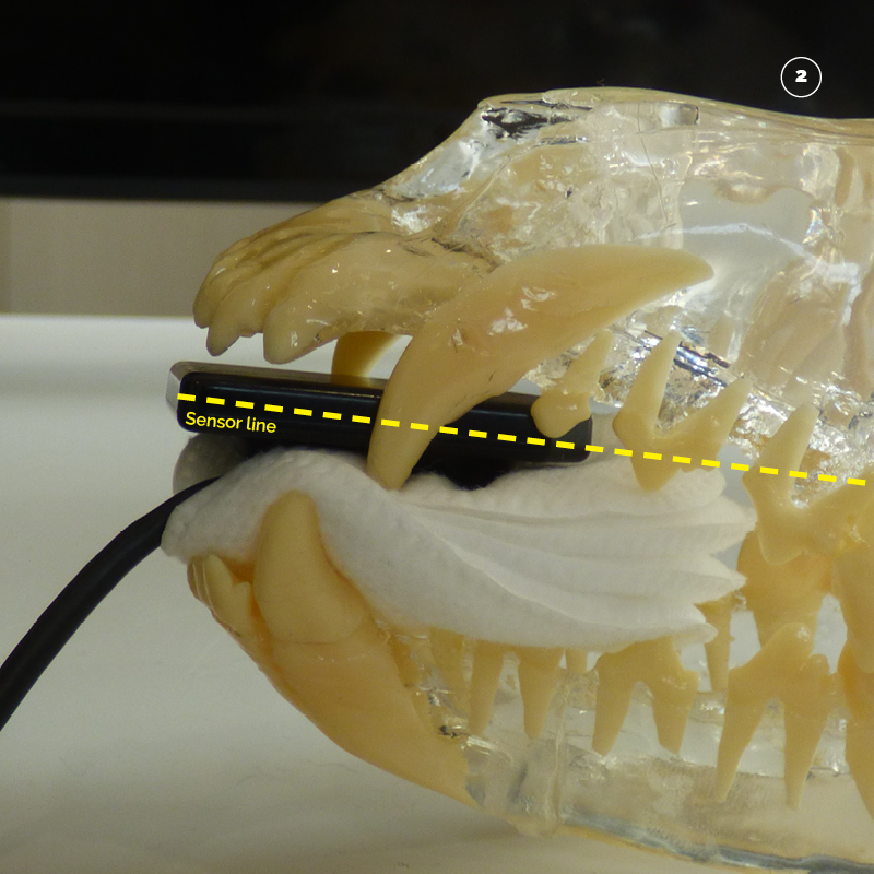
Step One. Identify the correct teeth.
The next image taken is the upper incisors 201, 202, and 203. Highlighted on the dental chart and outlined in the picture below.
Step Two. Placing the sensor .
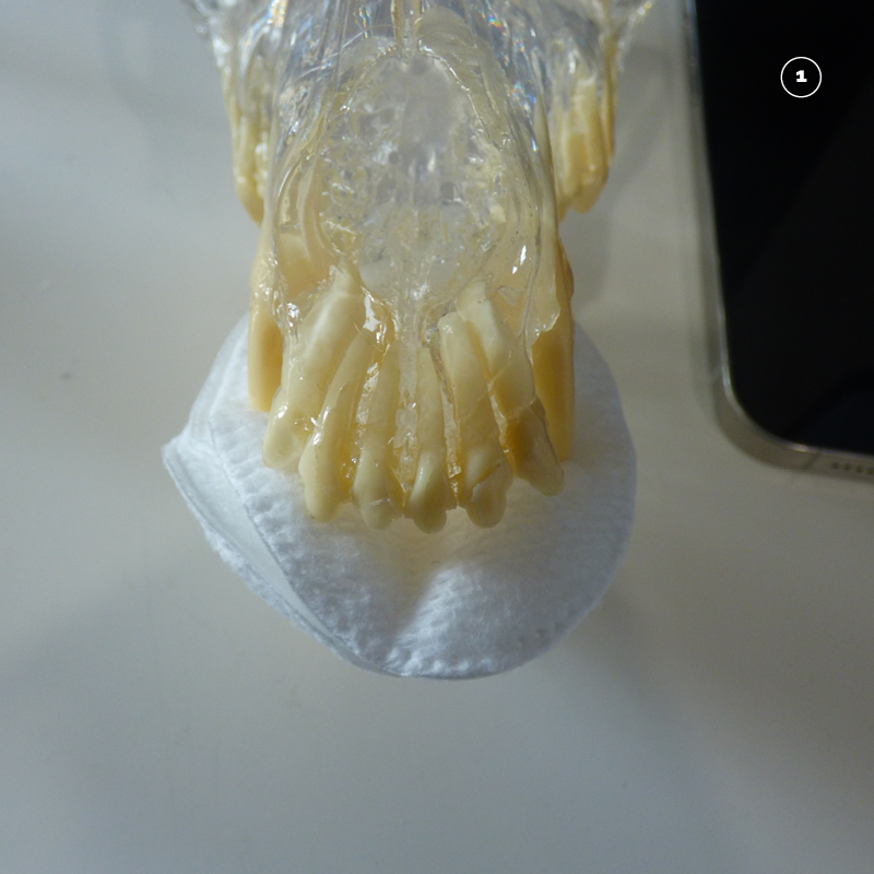
Make a cradle to hold the sensor in place by placing some swabs on the lower canine and incisor teeth.
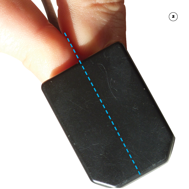
Holding the sensor with the forefinger and thumb place the sensor in the mouth.
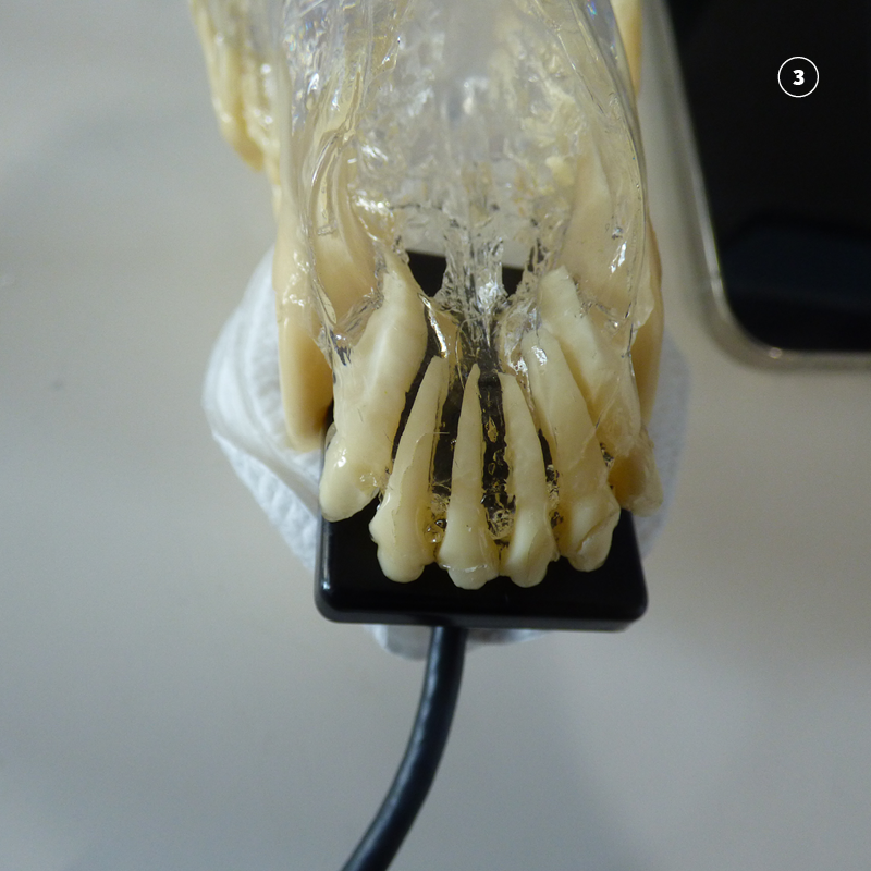
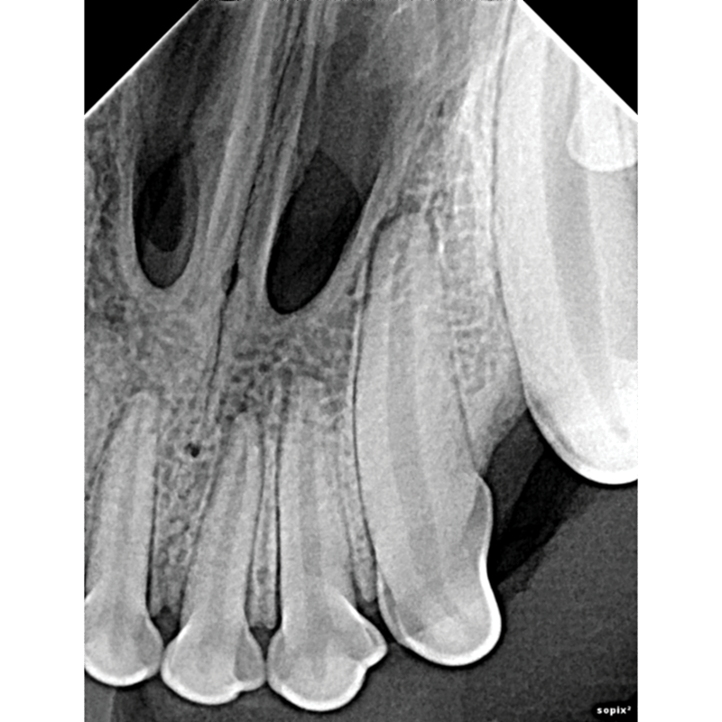
Make sure that the cusps of the crown are at the edge of the sensor so that it is far enough in the mouth to capture the apex of the third incisors (103 and 203) roots.
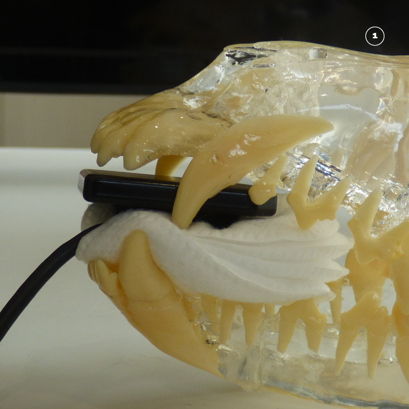
Step Three. Position the tube head opposite the sensor so that the beam covers the sensor.
With the incisor teeth place the tube head opposite the sensor rostral. Look down the cone to make sure that the center of the cone is aligned with the sensor wire where it connects to the sensor. This will always align the beam to cover the sensor.
Step Four. Roll the tube head to the correct angle.
As the beam is already aligned with the sensor. Calculate the correct angle using the bisecting angle technique and roll the tube head up to the right position.
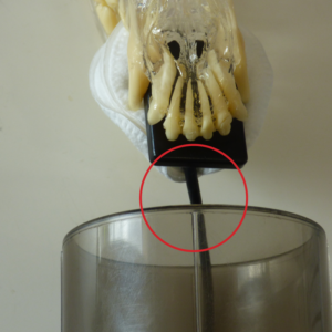
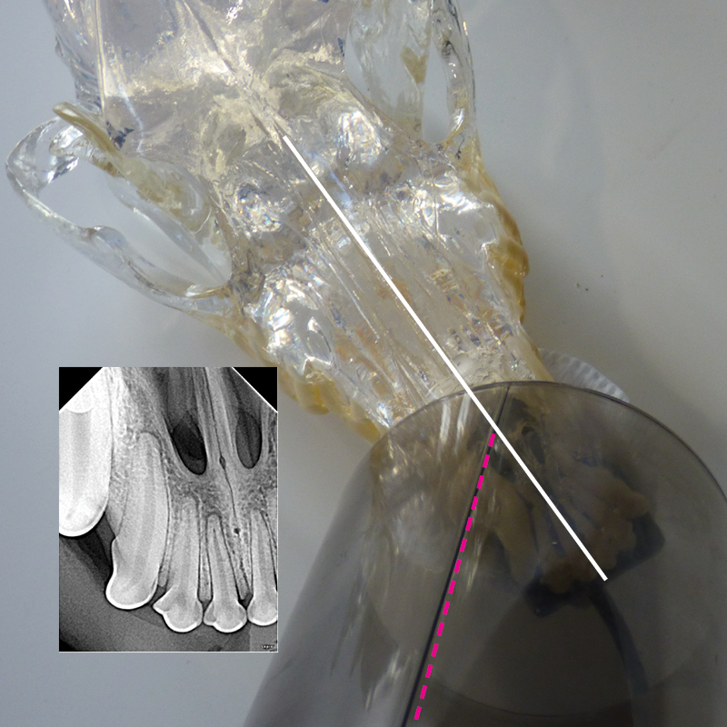
Visualise the patient from a lateral point of view.
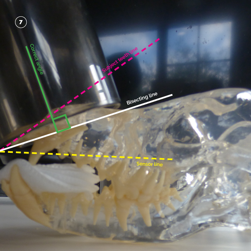
Think of the lines you are drawing going from outside of the mouth inwards when you visualise the line of the sensor. Note how the yellow dashed line runs from the outside along the sensor.

Visualise adding line running through the center of the subject teeth.
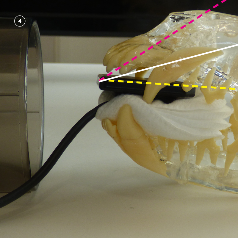
Visualize a third line that bisects (half’s) the angle. Pictured in white.
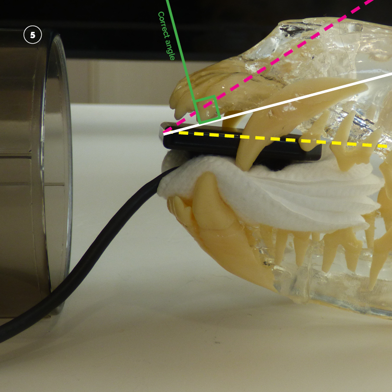
The correct angle will be perpendicular (90 degrees to) the white bisected angle. Pictured in green.
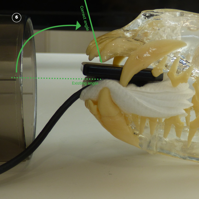
The tube head is rolled up to the correct angle to perfectly capture and image that is dimensionally and lineally correct.
Tube head at correct angle.
Step Five. Tube head orientation to patient mid-line.
The standard orientation for upper incisor teeth is along the mid-line. This is best for small and medium dogs and feline patients. In large dogs it may be necessary to split the incisors into two views of the left and right incisors. In this case the relationship to the mid-line changes slightly to the left for 101, 102, and 103 and slightly to the right for 201, 202 and 203. Offset by 10-20 degrees to capture the perfect image if splitting. If not remain along with the mid-line.
101, 102 and 103
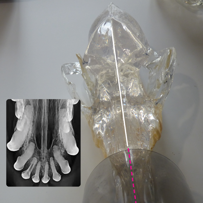
All upper incisors
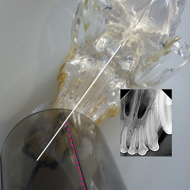
201, 202 and 203
Step Six. Radiation Factors.
The standard factors with a digital sensor are as follows:
| Patient Size | Location | KV | MAS |
| <= 15Kg | Maxillary Incisors | 60 | 0.100 |
| > 15Kg | Maxillary Incisors | 60 | 0.125 |