Step One. Identify the correct teeth.
The Next image taken is of the mandibular canine. Highlighted on the dental chart and outlined in the picture below.
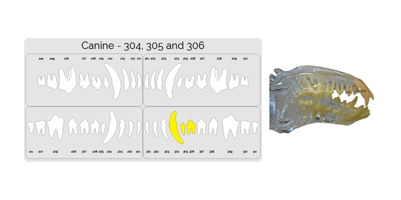
Note: The numbers appear reversed as the patient is in dorsal recumbency.
Step Two. Placing the sensor
Place the patient into dorsal recumbancy.
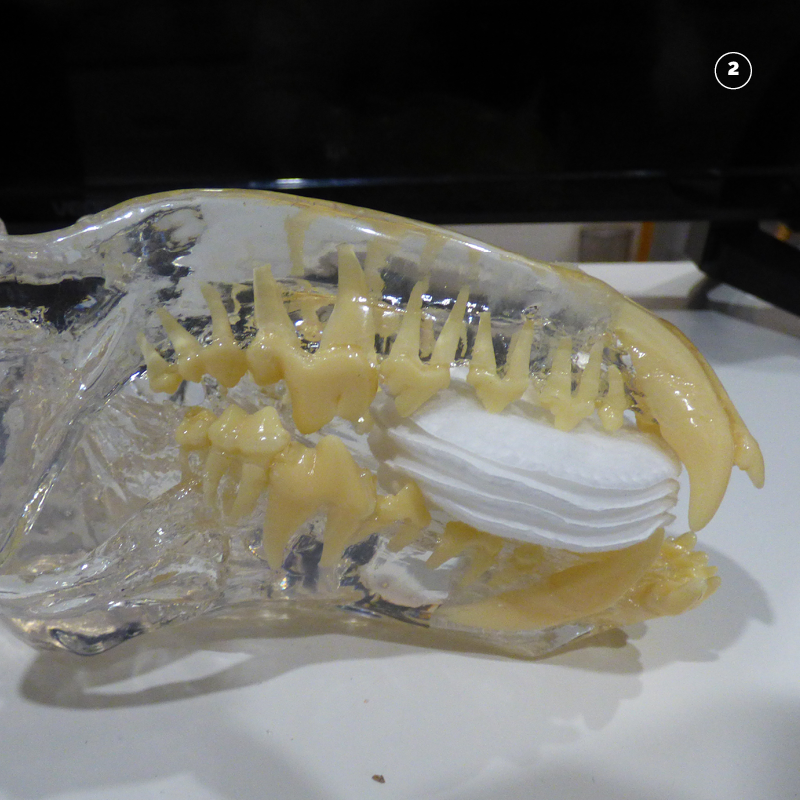
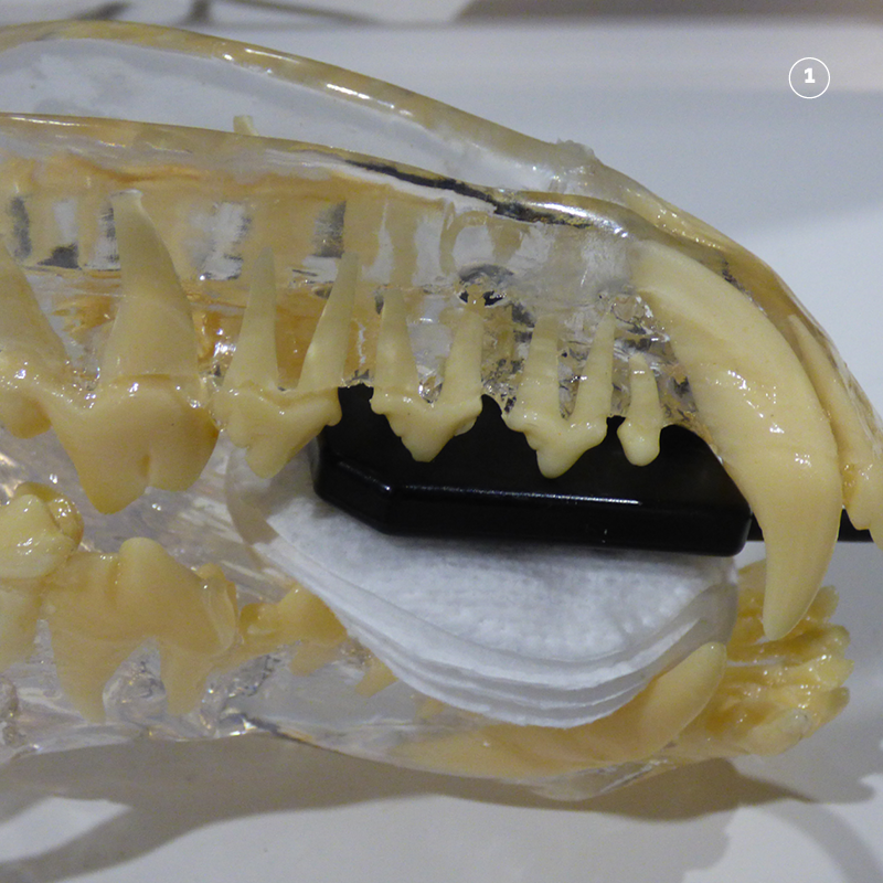
Make a cradle to hold the sensor by placing swabs behind the upper canine teeth.
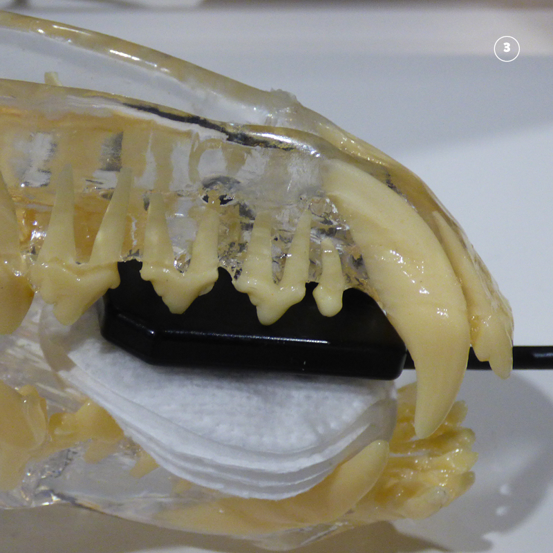
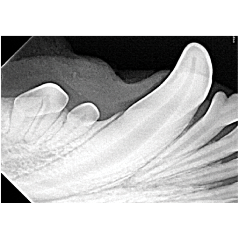
Place the sensor in the mouth with the forward corner of the sensor just behind the curve of the lower canine tooth. Ensure that the cusps of the premolars are aligned 1mm inside the sensors boundary.
For large dogs this position will capture a clear image of the root and periodontal structures of teeth 304, 305, 306. If an image of the crown is required to confirm fracture or other pathology refer to position 4.
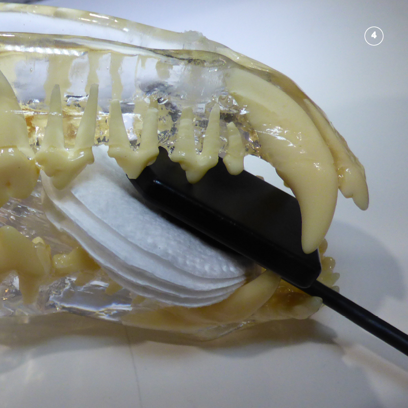
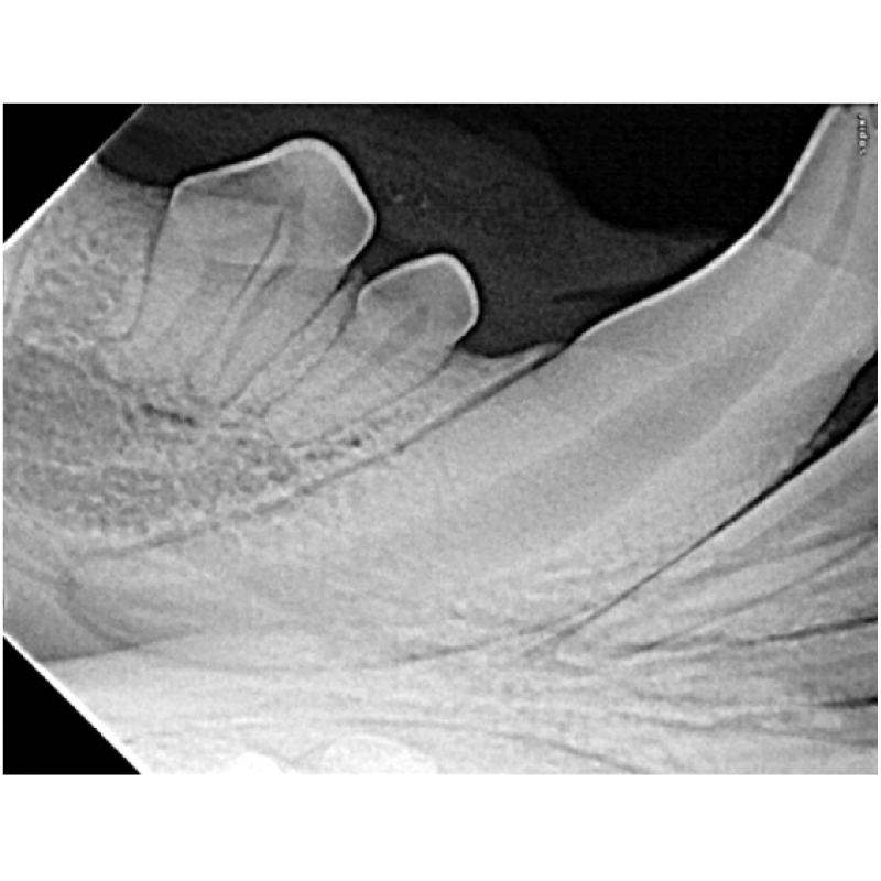
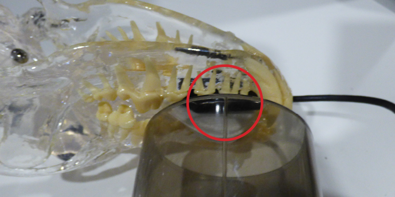
To capture the crown position the sensor with the outside front corner of the sensor directly below the cusp of the crown of the lower canine. Marked with red circle. On small and medium dogs this will capture the entire tooth. On larger dogs it will capture the crown of the tooth.

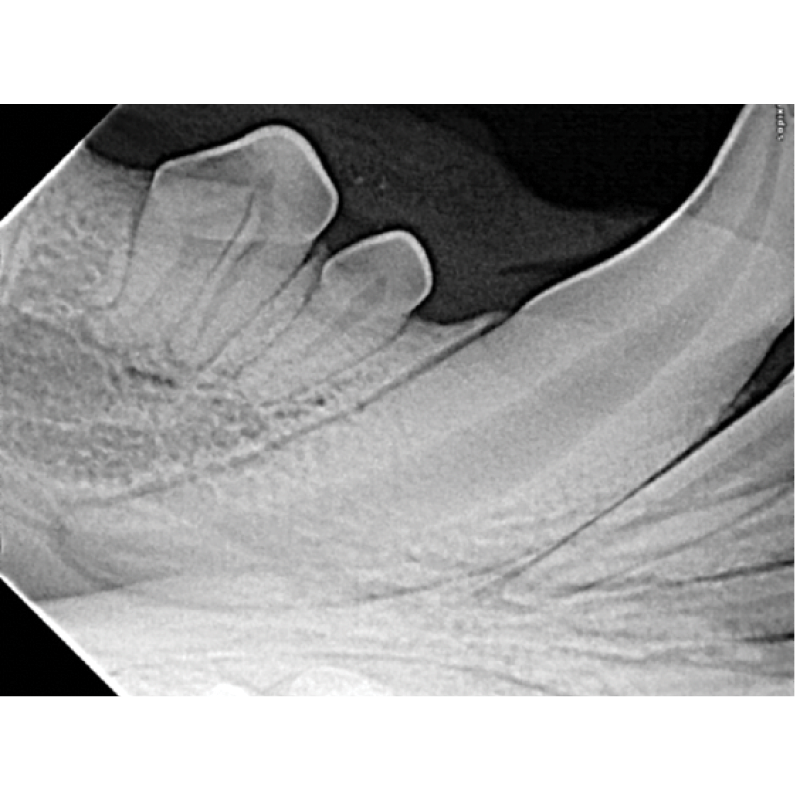
Image captured from position 4. Note the crown is captured but the apex of the root is absent.
Step Three. Position the tube head opposite the sensor so that the beam covers the sensor.
Place the cone opposite the sensor. Make sure that the entire cone covers the sensor. See through cones make this easy as you can look through the cone to see the sensor and teeth. Sometimes its necessary to retract the lips to see the sensor in the open mouth.
With a see through cone the sensor can be lined up with the central line of the cone to ensure the beam covers the whole of the sensor.
Step Four. Roll the tube head to the correct angle.
As the beam is already aligned with the sensor. Calculate the correct angle using the bisecting angle technique and roll the tube head up to the right position.
Start by visualising the view from the side.
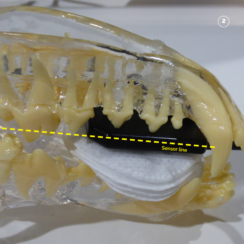
Visualise a line that moves along the sensor from the outside of the mouth inwards. This is the long side of the sensor. Marked in yellow.
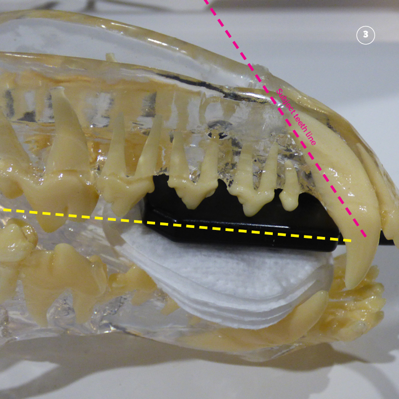
Next visualise a line through the centre of the teeth from cusp of the crown to apex of the root. Marked in pink.

Bisect (half) the angle between the yellow sensor line and the pink tooth line. Marked in white.
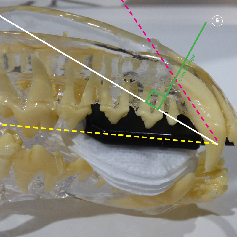
The correct angle is then calculated as perpendicular (90 degrees to) the white line that bisects (half’s) the angle of the sensor line (yellow) and the tooth line (pink). Marked in green.
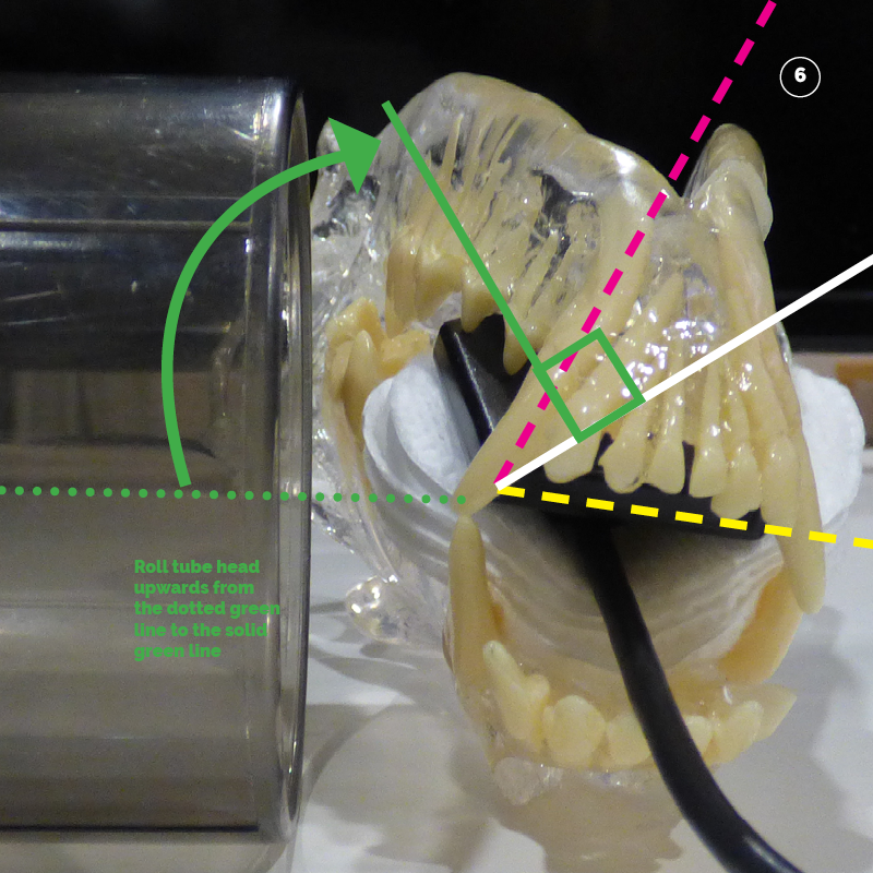
The tube head can then be rolled up to the correct angle.
Tube head rolled up to the correct angle.
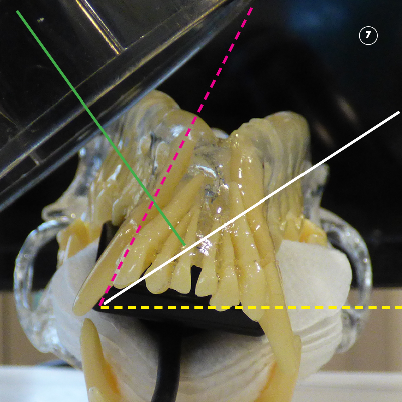
Step Five. Tube head orientation to patient mid-line.
The standard relationship for the canine tooth and first premolars is perpendicular to the mid-line.
Step Six. Radiation factors.
The standard factors with a digital sensor are as follows:
| Patient Size | Location | KV | MAS |
| <= 15 Kg | Mandibular Canine and Premolars 305 and 306 | 60 | 0.100 |
| > 15 Kg | Mandibular Canine and Premolars 305 and 306 | 60 | 0.125 |