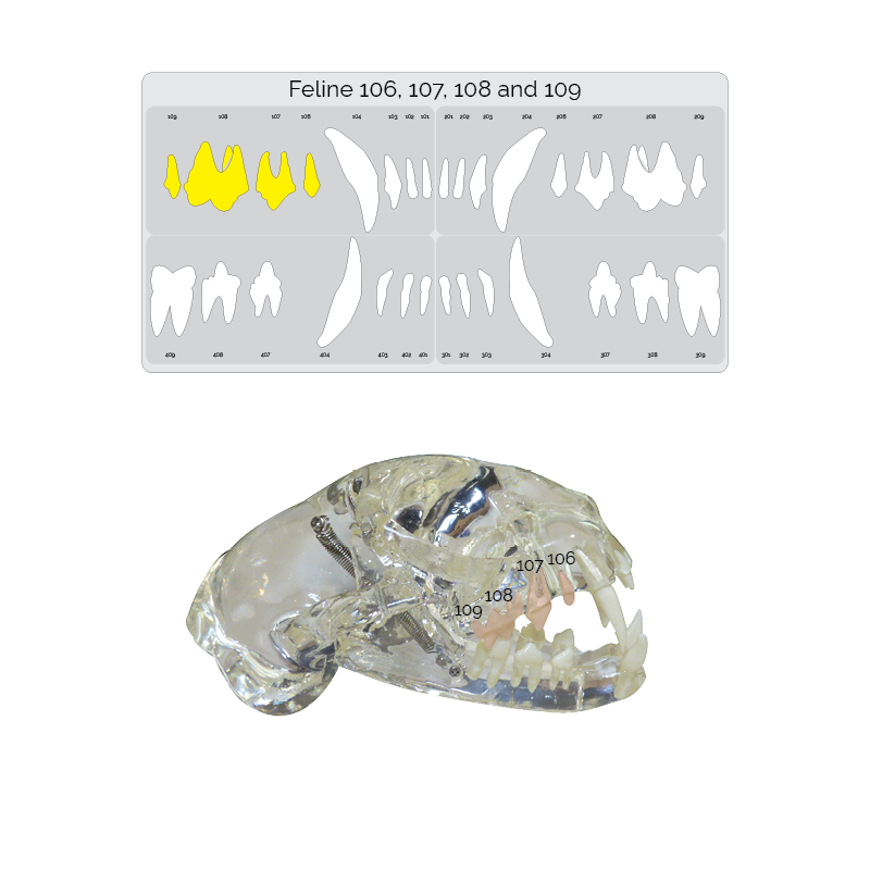
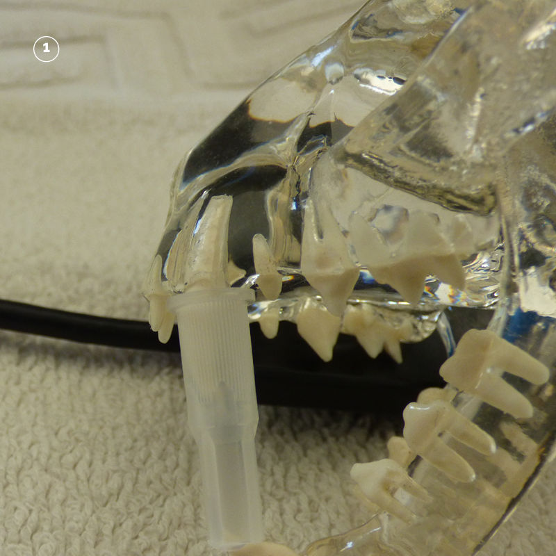
Step One. Identify the correct teeth.
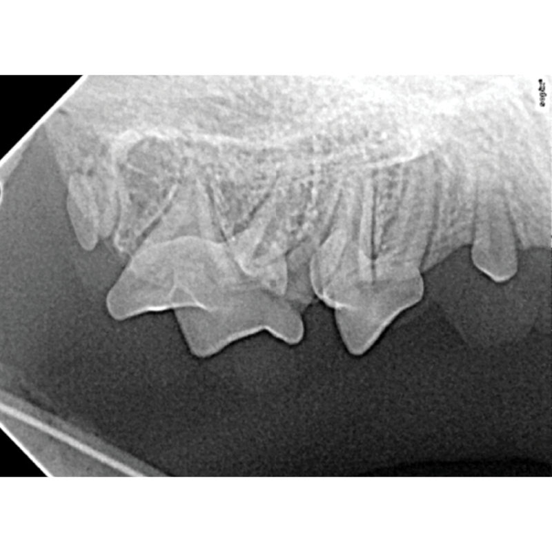
The Next image taken is of the maxillary premolars and molar teeth. Highlighted on the dental chart and outlined in the picture below. The technique is repeated for 206 – 209 located opposite.
Step Two. Placing the sensor
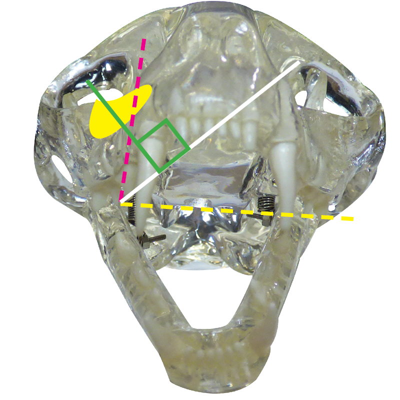
Feline anatomy makes it difficult to use the standard intra oral, bisecting angle technique. The zygomatic arch (marked in yellow) is almost always super imposed on top of the teeth if an image is taken intra orally.
Note how the correct beam angle passes through the zygomatic arch thus super imposing it on top of the teeth. This results in a strong opacity rendering the image undiagnostic.
The solution is to use an EXTRA ORAL BISECTING ANGLE TECHNIQUE. This technique reverses the superimposition placing the teeth on top of the zygomatic arch for a clear diagnostic image.
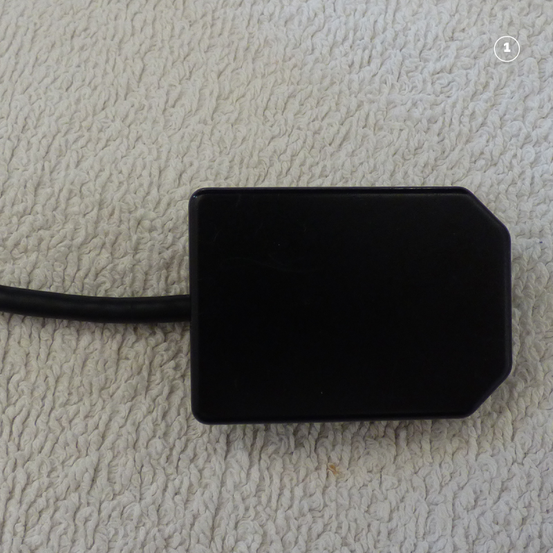
Place the sensor on the operating table.
Place the patient with the mouth open on top of the sensor. Ensure that the mouth is only temporarily held open.
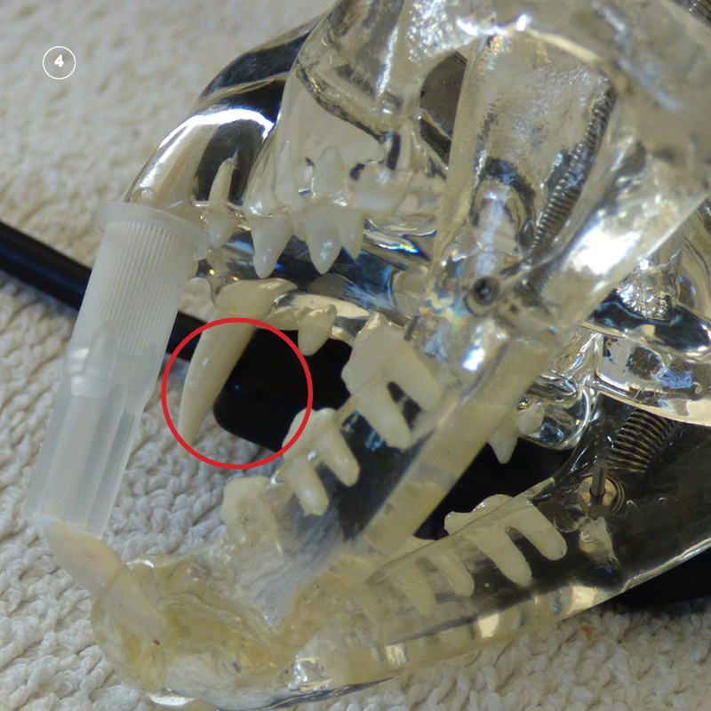
Move the sensor into a position where the cusps of the 107 and 108 (marked in pink) are just inside the sensor boundary (marked in blue).
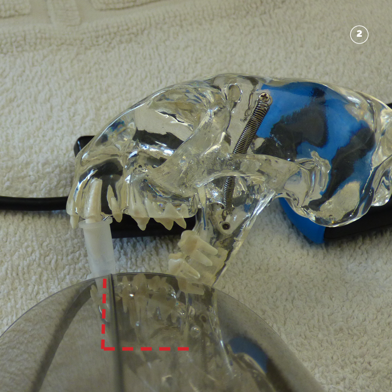
Check that the outside edge of the sensor in just behind 104 combined with step 3 this will ensure that the sensor is in exactly the right location.
Marked with red circle.
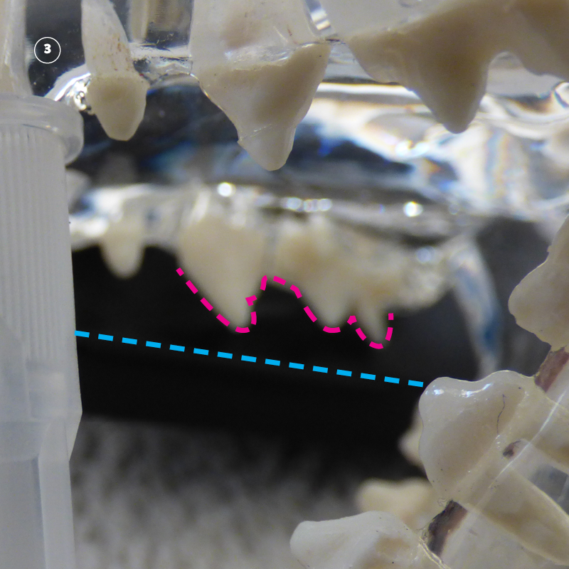
Step Three. Position the tube head opposite the sensor so that the beam covers the sensor.

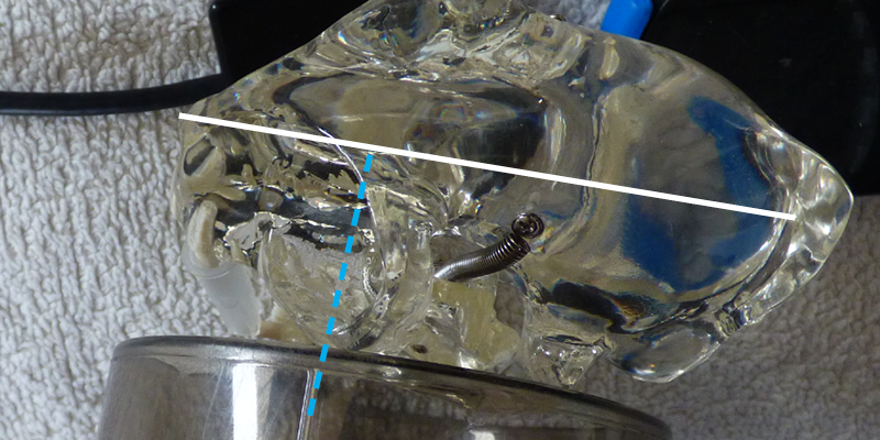
Start by placing the tube head perpendicular to the mid-line of the animal. This can be achieved by visualizing a line that starts at the cusp of 104 and passes through the cusp of 204. Marked in blue.
Move the tube head down and across so that the center of the cone is in line with the center of the sensor.
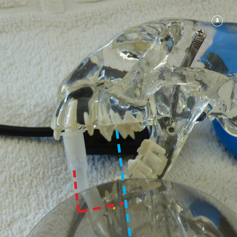
The result is that the cone is lined up with the center of the sensor. A guide is that the central line of the cone will be directly between teeth 107 and 108. Marked with a blue line. This will ensure that the beam is covering the sensor.
Step Four. Roll the tube head to the correct angle.
As the beam is already aligned with the sensor. Calculate the correct angle using the bisecting angle technique and roll the tube head down to the right position.
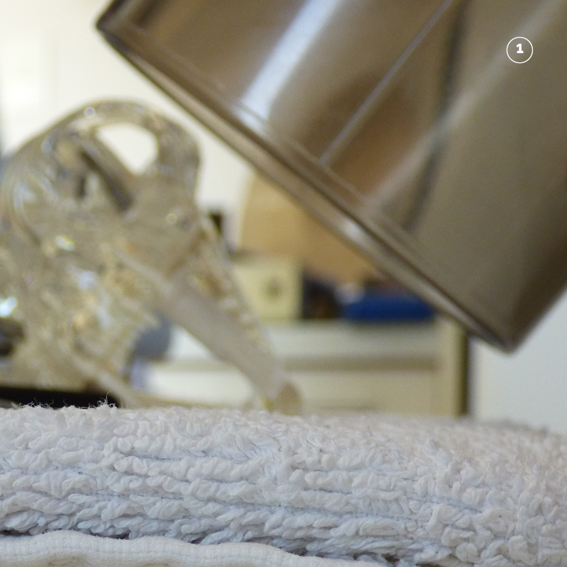
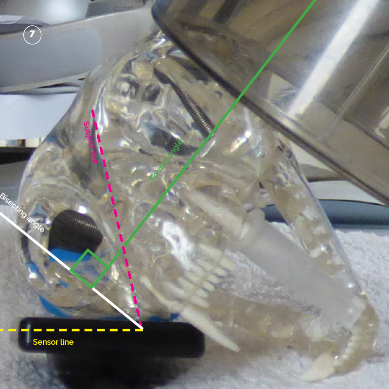
Start by visualising the patient from a rostral position.
Visualise a line through the front short side of the sensor running away from the patient. Marked in Yellow.
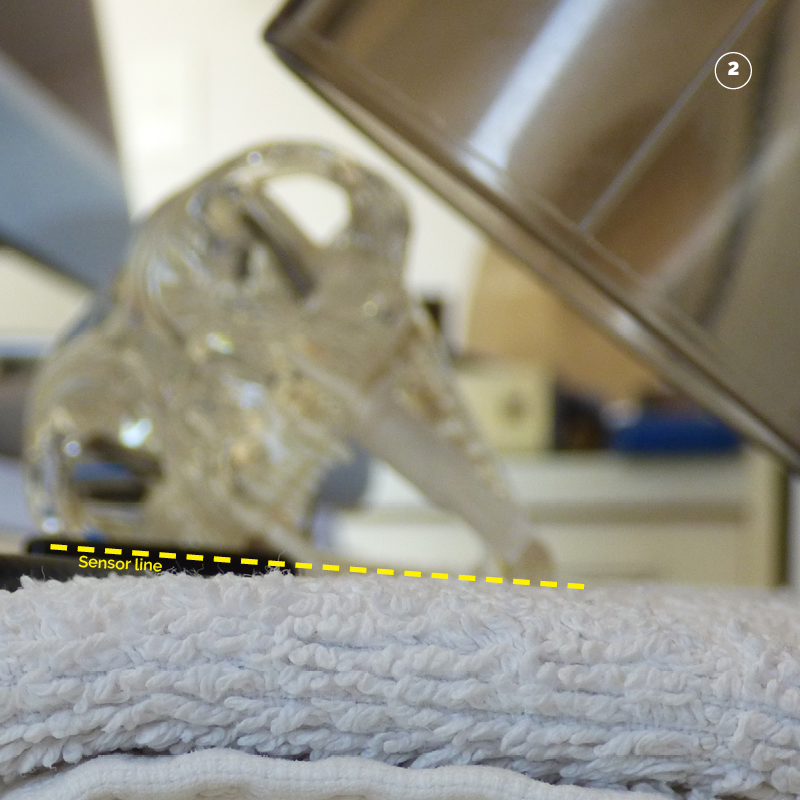
Then a line through the subject teeth. Marked in Pink.
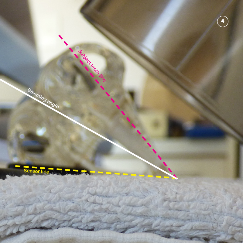
Bisect (half) the angle between the yellow sensor line and the pink tooth line. Marked in white.

The correct angle is then calculated as perpendicular (90 degrees to) the white line that bisects (half’s) the angle of the sensor line (yellow) and the tooth line (pink).
Marked in green.
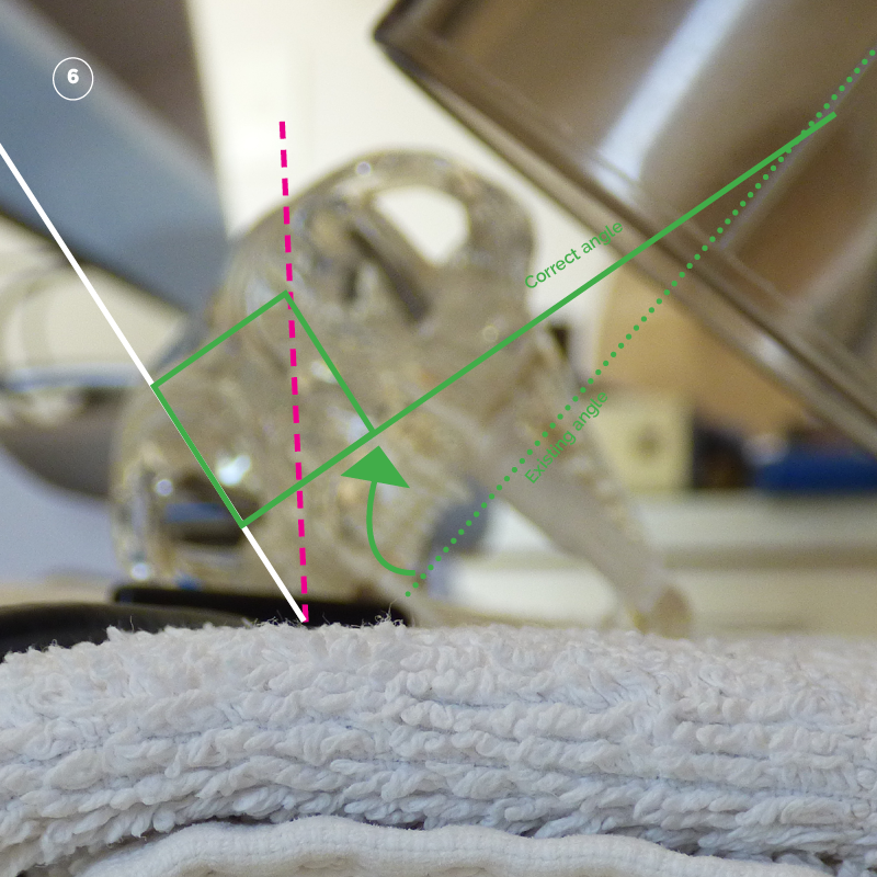
The tube head can be rolled down from its position covering the sensor from step three to the correct angle marked with the solid green line. Note as the tube head back moves down the cone pivots up.
Tube head at correct angle.
Step Five. Tube head orientation to patient mid-line.
The standard relationship between the tube head and the mid-line is perpendicular to the mid-line.
Step Six. Radiation factors
The standard factors with a digital sensor are as follows:
| Patient | Location | KV | MAS |
| Feline | Maxillary Premolars and Molars | 60 | 0.160 |