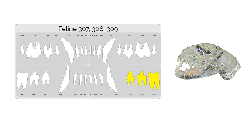
Step One. Identify the correct teeth.
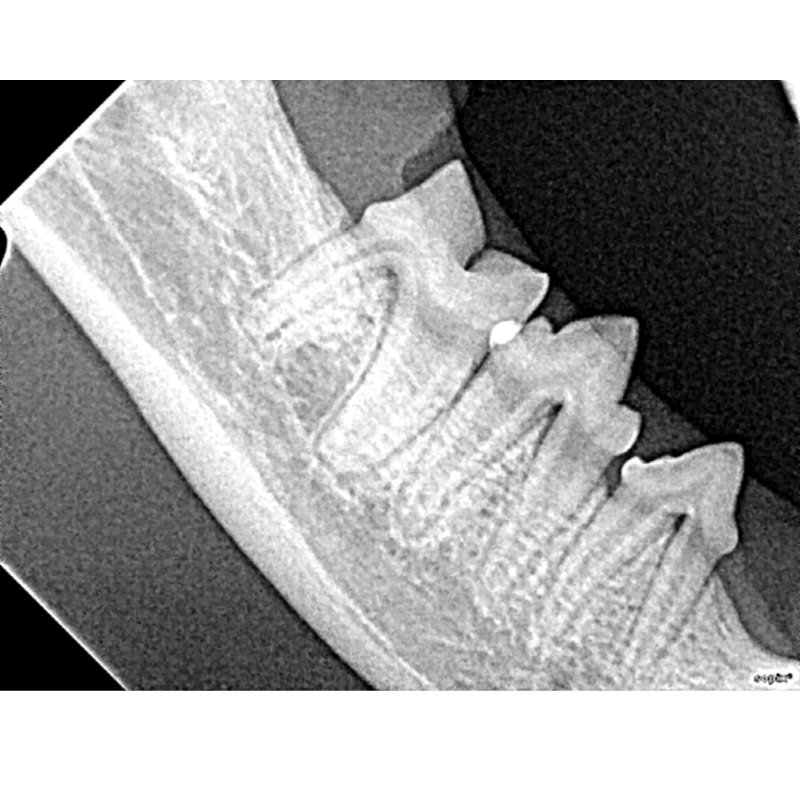
The next image taken is of the mandibular premolar and molar teeth. Highlighted on the dental chart and outlined in the picture below. Note that 407 -9 are opposite and the same technique is used.
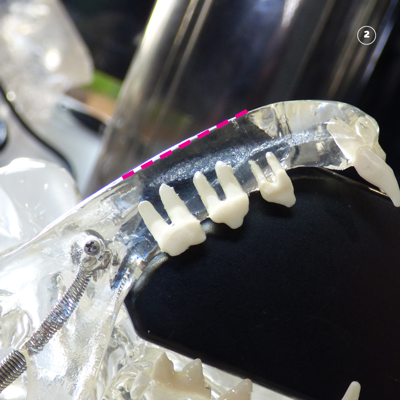
Step Two. Placing the sensor
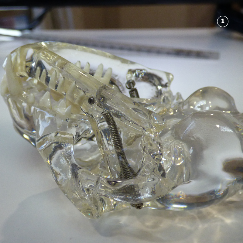
1 Place the patient in lateral recumbency.
2 Place the sensor into the mouth. It is shaped with two corners cut off at 45 degrees. This is so that it fits perfectly along the ventral edge of the mandible. Marked in pink
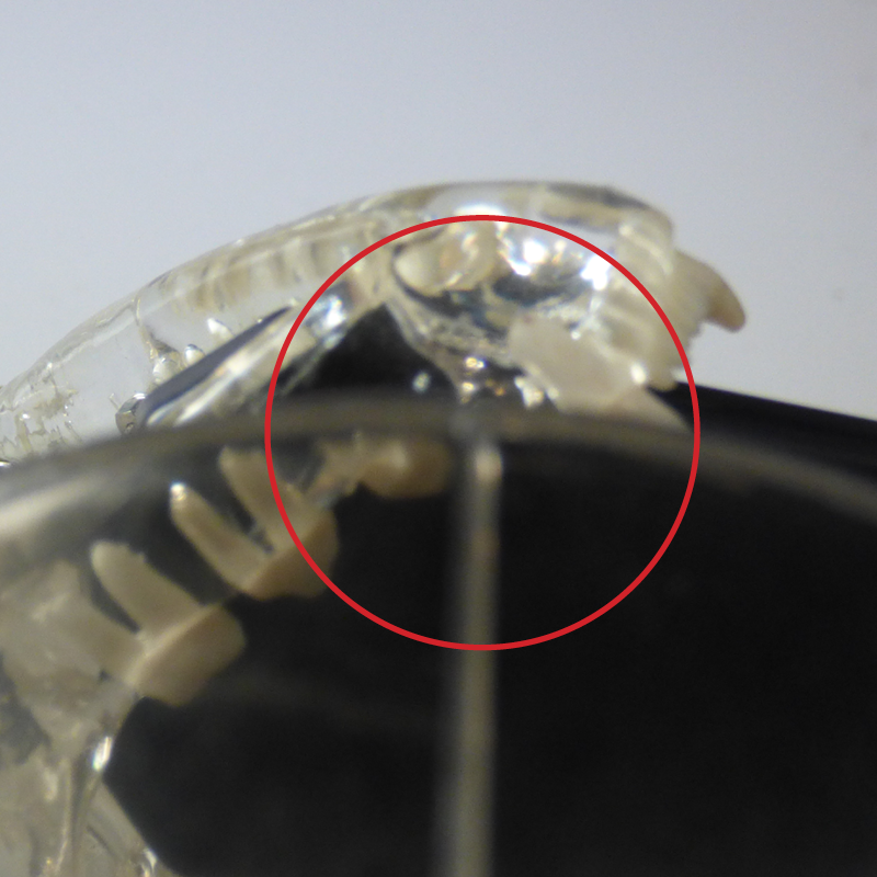
Step Three. Position the tube head opposite the sensor so that the beam covers the sensor.
Place the cone of the tube head opposite the sensor. With a see through cone the centre line can be visually aligned with the the sensor. Marked with a red circle.
This will ensure that the beam will cover the whole of the sensor.
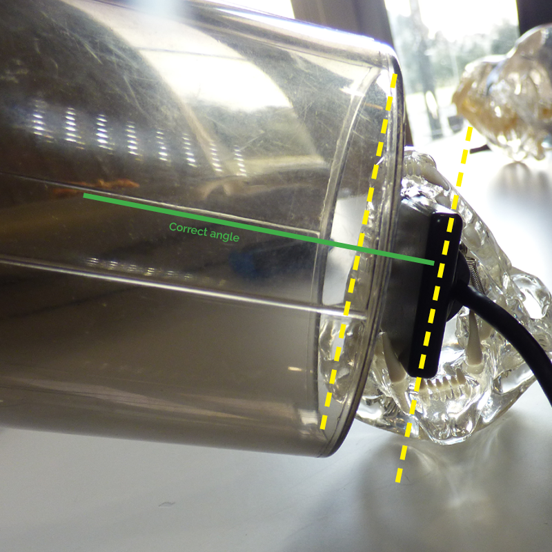
Step Four. Roll the tube head to the correct angle.
As the beam is already aligned with the sensor simply roll the sensor up so that the it is directly perpendicular to the sensor. This ensures that the generator is parallel to the sensor. Hence the name the parallel technique.
When the tube head is in the correct angle the base of the cone is parallel to the sensor.
Marked with the two yellow lines.
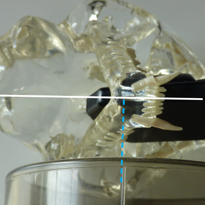
Step Five. Tube head orientation to patient mid-line.
The correct orientation is perpendicular to the mid-line.
Step Six. Radiation factors
The standard factors with a digital sensor are as follows:
| Patient | Location | KV | MAS |
| Feline | Mandibular Premolars and Molars | 60 | 0.125 |