Step One. Identify the correct teeth.
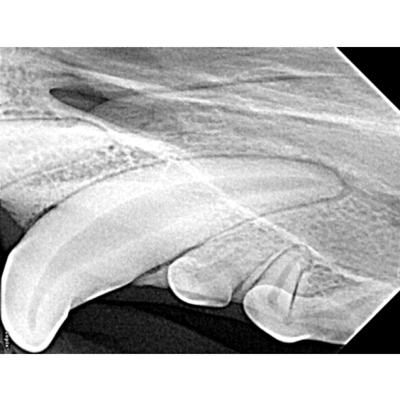
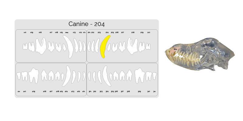
The next image taken is the upper canine 204. Highlighted on the dental chart and outlined in the picture below.
Step Two. Placing the sensor .
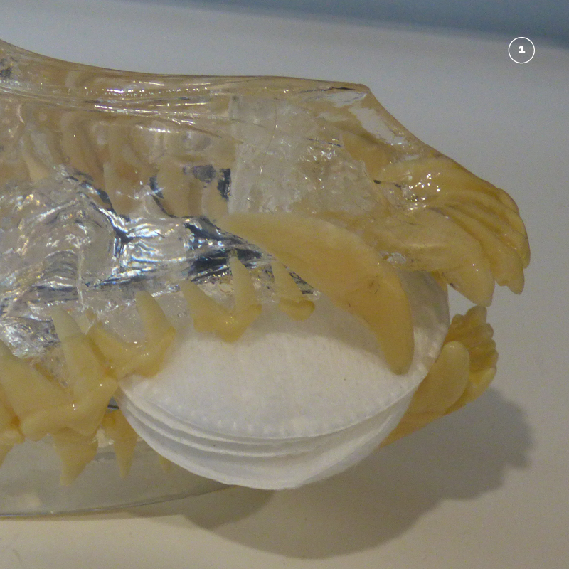
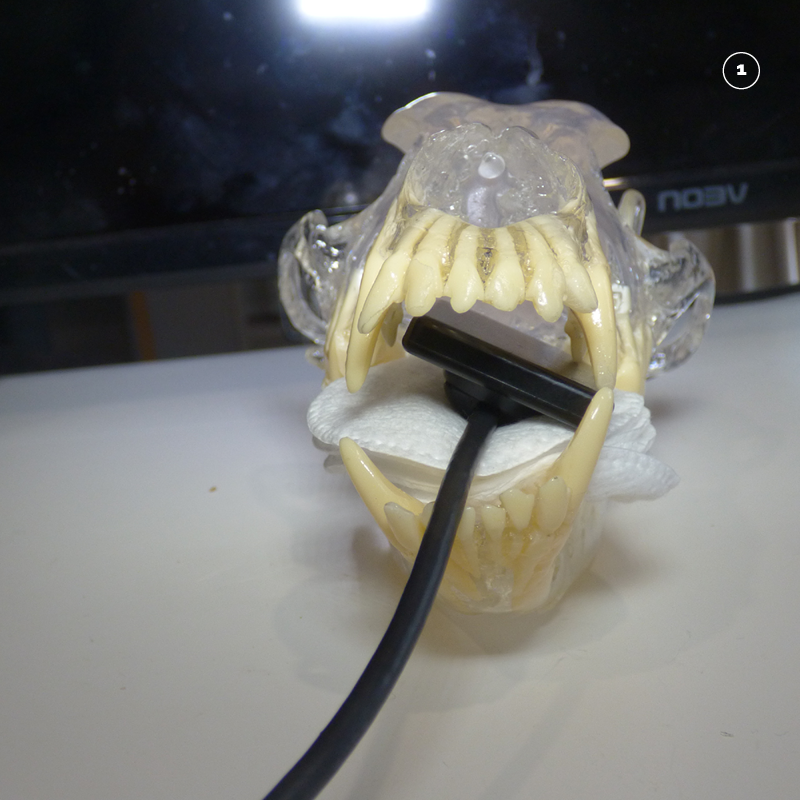
Make a cradle to hold the sensor in place by placing some swabs behind the lower canine tooth.
Place the sensor in the mouth so that the cusp of the canine tooth (104) rests on the front corner of the sensor. The sensor can be angled slightly into the mouth so that the whole of the tooth root is captured.
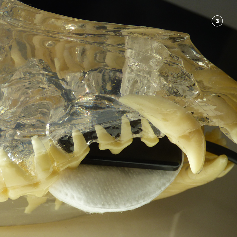
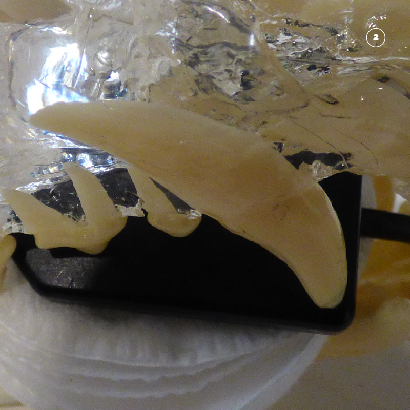
In very large dogs it is difficult to fit the entire tooth on a digital sensor. In these cases place the sensor with the outer corner of the sensor behind the curve of the crown of the tooth. Note how this moves the sensor caudally in the mouth so that a good image of the tooth root of 204 is achieved. A second image can the be taken of the crown in the standard position if necessary.
Step Three. Position the tube head opposite the sensor so that the beam covers the sensor.
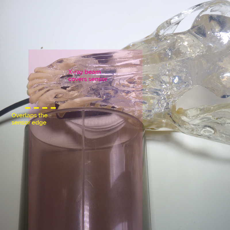
Place the cone opposite the sensor. Make sure that the entire cone covers the sensor. You can always see the outer end of the sensor so make sure that the cone overlaps this so that it is aligned properly. The overlap is marked in yellow and the beam in pink. See how the entire beam covers the sensor.
Step Four. Roll the tube head to the correct angle.
As the beam is already aligned with the sensor. Calculate the correct angle using the bisecting angle technique and roll the tube head up to the right position.
Start by visualizing the view from a rostral aspect.
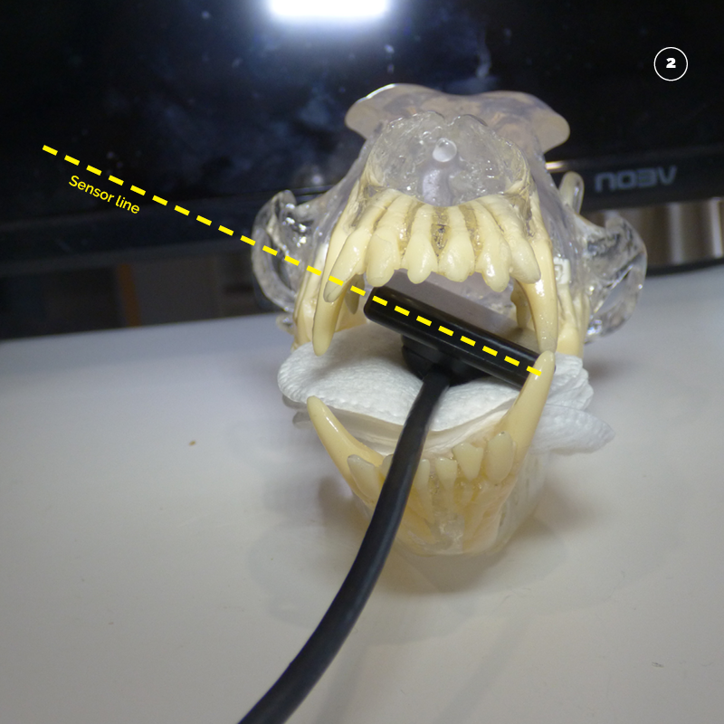
Visualize a line that moves along the sensor from the outside left of the mouth inwards. This is the short side of the sensor. Marked in yellow.
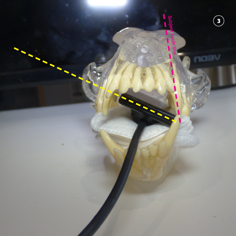
Next visualise a line through the centre of tooth 204 from cusp of the crown to apex of the root. Marked in Pink.

Bisect (half) the angle between the yellow sensor line and the pink tooth line.
Marked in white.

The correct angle is then calculated as perpendicular (90 degrees to) the white line that bisects (half’s) the angle of the sensor line (yellow) and the tooth line (pink). It is marked in green.
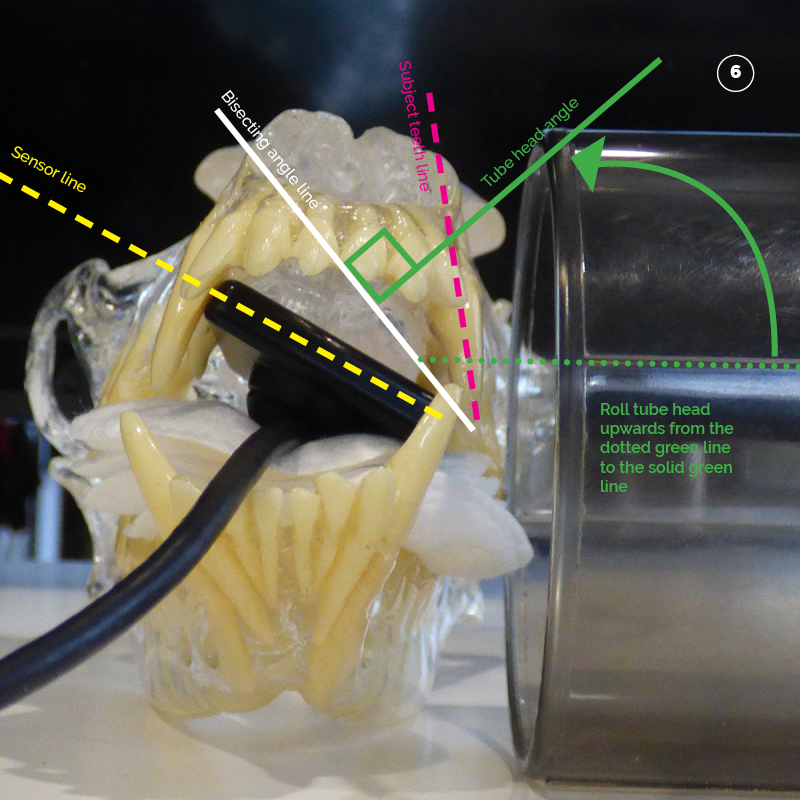
Once the correct angle is calculated simply roll the tubehead from its position in step 3. This ensures that the beam covers the sensor and that the tubehead is at the correct angle. Pictured in 6 and 7.
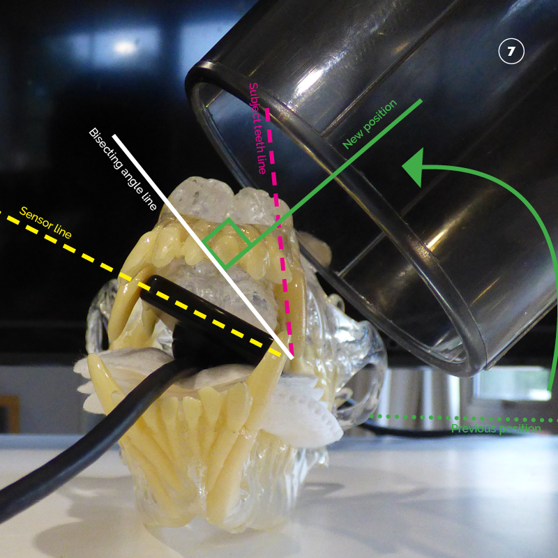
Tube head at the correct angle.
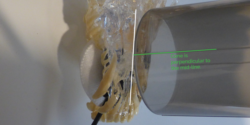
Step Five. Tube head orientation to patient mid-line.
The standard orientation for upper canine teeth is perpendicular to the mid-line.
Step Six. Radiation factors.
The standard factors with a digital sensor are as follows:
| Patient Size | Location | KV | MAS |
| <= 15 Kg | Maxillary Canine 204 | 60 | 0.125 |
| > 15 Kg | Maxillary Canine 204 | 60 | 0.160 |